CAREY FOSTER BRIDGE
INTRODUCTION
We know that if we want to measure the resistance which is above one ohm then we use a Wheatstone bridge but if the resistance is less than one ohm then we use a kelvin or kelvin double bridge to find the resistance in this case.
But how can we find the value of intermediate resistance i.e the resistance which ranges from 1Ω to 0.1MΩ? So to find the resistance of such resistance, we use a special kind of circuit bridge called the Carey foster bridge.
However, we can find the resistance of this range type by the Wheatstone bridge but the Carey foster bridge can also be used to measure the small differences between the two large resistors.
So in this article, we are going to discuss everything about Carey foster bridge, so let’s start…
WHAT IS CAREY FOSTER BRIDGE?
Carey foster is nothing but is a variant of Wheatstone bridge because it runs on the principle of Wheatstone bridge i.e principle of null deflection of the galvanometer.
In electronics, Carey foster is bridge is an electrical circuit that is used to find the medium resistance or used to measure the small differences between the two large resistance.
It is invented by the scientist Carey foster as the variant of the Wheatstone bridge. He first described this bridge in 1872 paper “On a Modified Form of Wheatstone’s Bridge, and Methods of Measuring Small Resistances” (Telegraph Engineer’s Journal, 1872–1873, 1, 196).
HOW TO USE CAREY FOSTER BRIDGE?
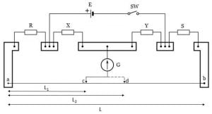
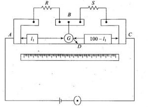
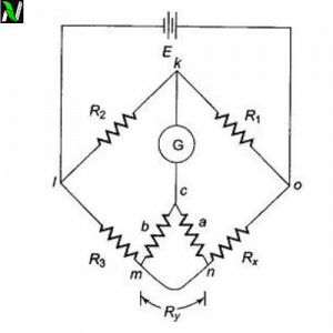
So, how can we use Carey foster bridge? In the above figure, you can see four resistance namely R, X, Y, and S . R and S are the resistance to be compared, and X and Y resistance are such that they have nearly equal resistance.[latexpage]
The edges which you are seeing are the copper busbars of almost zero resistance. You can also see a galvanometer whose one end is connected to the copper busbar between the resistance X and Y and its other end are free to move which acts like a jockey.
The jockey of the galvanometer is slid on the thin wire ab of the bridge until the galvanometer shows null deflection.
PROCEDURE TO USE
Step by step procedure to operate the Carey foster bridge. Consider these points during performing Carey foster bridge experiment.
-
- First, place the known resistance in position S.
- Then place the unknown resistance in position R.
- Now moves the jockey of the galvanometer over the wire ab until the current through the galvanometer becomes zero. Let’s assume c is the point where the galvanometer shows null deflection.
- Note the length of the point c from point a on the bridge, let’s take the length $l_1$ as shown in the above figure.
- Now interchange the position of the resistance R and S and again moves the jockey to obtain the balanced point.
- Let’s assume d is the point of null deflection and its length from point a is $l_2$.
- If σ is the resistance per unit length of the wire ab of the bridge then the difference between the resistance X and Y is equal to the sigma times the difference of the length of the balanced point.$$R-S=\sigma\left(l_2-l_1\right)$$
If you want to find the value of low unknown resistance R then replace S with a copper busbar that can be assumed to be of zero resistance.
In practical use, if the bridge is unbalanced, then the galvanometer is shunted with a low resistance to avoid burning it out. It is only be used at full sensitivity when the expected measurement is close to the null point.
HOW TO MEASURE σ?
If you want to measure σ (resistance per unit length) then put the known resistance that is less than the resistance of the wire in place of R. And use the copper busbars as a resistor that is assumed zero resistance in place of S.
$$\sigma=\frac{R}{l_2-l_1}$$
Where S is assumed to be zero.
DERIVATION FOR BALANCED EQUATION
Let’s consider the above figure. R and S are the resistance that is to be compared and X and Y are the resistance of almost equal resistance lie in the inner gap of the bridge.
Consider α is the resistance of left side copper busbar and β is the resistance of right side copper busbars. If c is the null point of the bridge then $l_1$ be the left side resistance length and $(100-l_1)$ be the right side resistance length. The total left hand side resistance is $R+\sigma(l_1+\alpha)$ and total right hand side resistance is $S+\sigma(100-l_1+\beta)$. But if d is the null point, then the total resistance at the left and right hand side is $R+\sigma(l_2+\alpha)$ and $S+\sigma(100-l_2+\beta)$.
At the balanced condition it is considered as wheatstone bridge, so applying balanced condition property at point c having resistance length $l_1$, we have-
$$\frac{X}{Y}=\frac{R+\sigma(l_1+\alpha)}{S+\sigma(100-l_1+\beta)}$$
Now add 1 to both side, we get-
\begin{equation}
\frac{X}{Y}+1=\frac{R+S+\sigma(100+\alpha+\beta)}{S+\sigma(100-l_1+\beta)}
\end{equation}
Now interchange the resistance R and S, so in this case, point is d is the balanced point having $l_2$ resistance length then, we have –
$$\frac{X}{Y}=\frac{S+\sigma(l_2+\alpha)}{R+\sigma(100-l_2+\beta)}$$
Adding 1 to both side, we get-
\begin{equation}
\frac{X}{Y}+1=\frac{R+S+\sigma(100+\alpha+\beta)}{R+\sigma(100-l_2+\beta)}
\end{equation}
If you see clearly, then you will see that both equations have the same left-hand side and also they have the same numerator. If they have the same numerator and left-hand side then their denominator must be equal.
Equating denominators of both equation, we get-
$$\displaystyle{S+\sigma(100-l_1+\beta)=R+\sigma(100-l_2+\beta)}$$
$$\implies\; R-S=\sigma(l_2-l_1)$$ Thus, from this we can conclude that, the difference between the resistance R and S is resistance of the bridge wire between $l_2$ and $l_1$. The bridge is says to be most sensitive when all the resistance R, X, Y and S are in comparable magnitude.
ADVANTAGES OF CAREY FOSTER BRIDGE
Some advantages of Carey foster bridge is listed below:
- It gives an accurate measurement of the difference between the resistance.
- Only one unknown resistance is sufficient to measure the difference between the resistance.
- Need less maintenance and operating cost.
- Less chance of human errors.
- Not a very complex construction, it is easy to construct.
DISADVANTAGES OF CAREY FOSTER BRIDGE
Some disadvantages of Carey foster bridge is listed below:
- Slide wire or jockey needs calibration after regular use. It should be calibrated to avoid any errors.
- Need replacement of electric components after a time, because, with time, some characteristics properties of sensitive parts of the components like resistance and galvanometer are not the same.
- No scope for digital measurement.
APPLICATIONS OF CAREY FOSTER BRIDGE
Some applications of Carey foster bridge is listed below:
- It is used to measure the difference between the resistance.
- It can be used to find the specific resistance of the wire.
- It is used to compare the two equal resistances.
- It is used to measure the unknown resistance.
Stay tuned with Laws Of Nature for more useful and interesting content.

![Wheatstone bridge | working principle, construction and its derivation [class 12].](https://www.natureof3laws.co.in/storage/2021/06/wheatstone-bridge-300x240.jpg)
