Inside Story
HYDRODYNAMICS : FLUID IN MOTION

FLUID MOTION
STREAMLINE FLOW
It is the type of flow in which the path taken by the fluid particles under a steady flow is streamline in the direction of the fluid velocity at that point.
LAMINAR FLOW

In this type of flow, fluid flows in steady state and moves in the form of layers of different velocities and never intermix while flowing.
TURBULENT FLOW
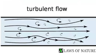
It is also a type of the fluid motion in which velocity of the particles is greater than its critical velocity and particles become irregular during motion.
CRITICAL VELOCITY
It is the maximum velocity of the fluid up to which the flow is streamline and above which it become turbulent is called critical velocity.
Mathematically ;
Vc = kη/ρr , where η is viscosity of liquid, ρ is the density of the liquid, r is the radius of the tube.
REYNOLDS NUMBER
It is the number scale which determines the nature of the motion of the liquid through the pipe.
Reynolds number is given as-
= (Inertial force per unit area/viscous force per unit area)
Mathematically;
N = ρvr/η
where v is the velocity of the liquid, r is the radius of the tube and ρ is the density of the liquid.
On the basis of Reynolds number, we have –
0
2000
3000


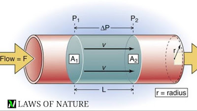
EQUATION OF CONTINUITY

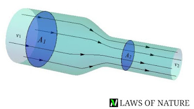
Equation of continuity says that if an incompressible and non viscous fluid flowing through a pipe of non uniform cross sectional area then the product of the velocity of the fluid and cross sectional area at every point inside the pipe remains the same.
Mathematically;
A1v1 = A2v2 , or Av = constant
This equation is known as equation of continuity.
BERNOULLI’S PRINCIPLE

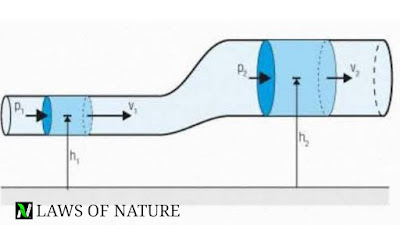
This principle states that, for a incompressible, non viscous fluid in a streamlined irrotational flow , the sum of the pressure energy, kinetic energy and potential energy at per unit volume remains constant at every cross sectional area throughout the liquid flow.
Mathematically it is given as ;
P + 1/2ρv^2 + ρgh = constant
Or P/ρg + h + v^2/2.g = new constant
*. If the fluid is flowing through a horizontal tube, the both ends at the same level, then the potential energy becomes zero because height is zero,(h=0)
P/ρg + v^2/2g = constant
*. If fluid is in rest inside the tube then velocity is zero everywhere in the pipe, in this case –
P1 + ρgh1 = P2 + ρgh2
P1 – P2 = ρg(h2 – h1)
APPLICATIONS OF BERNOULLI’S PRINCIPLE
SPEED OF EFFLUX

It is the speed of the liquid which flow through the small orifice (narrow hole) is equal to that which a freely falling body would acquire in falling through a vertical distance equal to the depth of the orifice below the free surface of the liquid.
Speed of efflux is given by v = √2gh
*. HORIZONTAL RANGE – when liquid flows out from a narrow hole which is at depth h below the free surface of the liquid of a fully filled tank of height H. Then it covers some horizontal distance from the foot of the tank and this horizontal distance called the range of the efflux.
Range of the efflux is given as –
R = velocity of efflux × time taken by the liquid to reach the ground.
Time taken by the liquid to reach the ground level is, T = √2(H-h)/g
R = √2gh × √2(H-h)/g = 2√h(H-h)
VENTURI-METER

It is a device used to measure the flow speed of incompressible , non viscous fluid using a U shaped manometer attached to it, with one arm at narrow end and one arm at broader end.
After applying Bernoulli’s principle –
v = √{2(ρm)gh/ρ}.[(a1^2/a2^2) – 1]^-1/2
where , ρ is the density of the fluid
ρm is the density of fluid in manometer
a1 and a2 are area of cross section
DYNAMIC LIFT OF A BALL DUE TO MAGNUS EFFECT

When a spinning ball is thrown in air, then it somehow deviate from its original path. This deviations arise due to the pressure difference between the upper and lower faces of the spinning ball , due to this Pressure difference ball experienced a upward lift by the net force acting upon it , is called Magnus effect.
Lift of an aircraft wings and blown off the roof without damaging the house are some examples where Magnus effect can be seen.
VISCOSITY
*. It is the tendency of the fluids to opposes the relative motion of its layer is called viscosity of the liquid.
*. Backward dragging force are also called viscous drag or viscous force.
*. According to Newton, viscous force ( F) between the two layers is given as –
F = -ηA(dv/dx) , where η is the cofficient of viscosity of the liquid.
A is the area of each layer and dv/dx is velocity gradient.
Here negative sign shows that viscous force act in opposite direction of the flow of the liquid.
COFFICIENT OF VISCOSITY
It is defined as the ratio of shearing stress to the strain rate.
η = (F/A)/(v/l) = Fl/vA
*. Dimensional formula is [ML^-1T^-1]
*. SI unit is poiseuille (Pl) or Pa.s or N/m^2 .s
*. In CGS system it unit is dyne/cm^2 called poise. 1 Pl = 10 poise.
*. For ideal fluid value of viscosity is zero.
*. Viscosity is due to transport of momentum.
*. Relative viscosity is = η/(ηwater)
STOKES LAW
Stokes law states that , if a sphere of radius r moves with velocity v through the liquid of viscosity η , then the drag force experienced by the sphere is given as –
F = 6πηrv
TERMINAL VELOCITY
It is the maximum velocity acquired by a body while falling through a viscous liquid called terminal velocity.
The constant terminal velocity attained by the sphere of radius r of density ρ while falling in the fluid of viscosity η and density σ is –
V(t) = 2r^2.(ρ-σ)g/9η
POISEUILLE FORMULA

It is the rate of volume of fluid coming out of the tube.
Mathematically it is given as-
V/t = πPr^4/8ηl ,
where P is pressure difference, η is cofficient of viscosity of fluid , l is the length of the tube and r the radius of the tube.
*. Series combination ( V1 = V2)
V/t = P/[(8ηl1/πr1^4) + (8ηl2/πr2^4)]
Here, P = P1 + P2
P1 and P2 is pressure difference between first and second tube.
*. Parallel combination ( P1 = P2)
V/t = P[(πr1^4/8ηl1) + (πr2^4/8ηl2)]
Here, V = V1 + V2


