POTENTIOMETER (MEASURING INSTRUMENT)
Around 1841, a method was described by the scientist Johann Christian Poggendorff, which helps in the measure of potential difference by the comparison of an unknown voltage to the reference known voltage.
Over time this method became a standard laboratory measuring technique and started widely using in laboratories to measure the potential difference by comparing an unknown voltage to a reference known voltage. And this technique is also taught to the students, who study physics in the 12th class.
We are talking about the potentiometer. In this article we are going to discuss everything about this measuring instrument, so let’s start…
WHAT IS POTENTIOMETER? BASICS
DEFINITION
A potentiometer is an instrument for measuring voltage or ‘potential difference’ by comparison of an unknown voltage with a known reference voltage.
If we add a sensitive indicating instrument, then a very little amount of electric current is drawn from the unknown voltage source. Since, we can produce the reference voltage by calibrating the voltage divider accurately, so a potentiometer can provide high precision measurements.
In the arrangement of a potentiometer, a part of a known voltage from a resistive slide wire is compared with an unknown voltage employing a galvanometer.
The sliding contact or wiper of the potentiometer is adjusted on the resistive slide wire and the galvanometer is connected between the sliding contact and the unknown voltage.
The changes in the galvanometer needle are observed and the sliding tap adjusted until the galvanometer shows zero deflection.
At that point, where the galvanometer didn’t draw any electric current from the unknown source, then, in this case, we can calculate the magnitude of voltage from the position of the sliding contact.
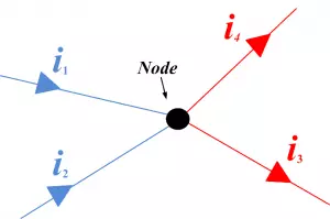
The null deflection method of measuring is very important in electrical physics because various devices are running on this principle. like – potentiometer, Wheatstone bridge, kelvin bridge, Carey foster bridge, etc.
WORKING PRINCIPLE
WORKING PRINCIPLE – The principle of a potentiometer is that the potential dropped across a segment of a wire of uniform cross-section area carrying a constant current is directly proportional to its length.
There are various school or college students, who face problems in understanding the underlying working principle behind the potentiometer because they have no good or authentic source in which this concept is explained very well.
So today we will understand the working principle of the potentiometer from scratch.
The basic working principle of the potentiometer is quite simple. Let’s consider this circuit below:

In the above circuit, suppose we have connected two cells in parallel, in which negative terminals of each cell are connected together and positive terminals of each cell are connected together through the galvanometer.
Now, here if the electric potential of each cell is exactly the same then there will be no current flowing through the galvanometer means the galvanometer show null deflection. This is on which the working principle of the potentiometer is based. So how it based on let’s see…
Let’s consider another circuit, actually, this is not another or any new circuit whereas it is the modified form of the above circuit, in which just the upper cell (driver cell) is connected across a resistor (black strip) through a switch and a rheostat, see figure below:
The resistor is such that it has a uniform electrical resistance per unit length throughout the length. So, due to this, the voltage drop per unit length of the resistor will be also equal throughout its length.
Suppose, by adjusting the rheostat, we get v volt voltage drop at per unit length of the resistor.[latexpage]
Now we see that the positive terminal of a standard cell (the cell which is connected to the galvanometer) is connected to point A on the resistor and the negative terminal of the same cell is connected with a galvanometer.
If we analyze this circuit then we will be found that it is the same circuit as fig. 1, both cells in fig. 2 are also joined in parallel such that their positive terminal are joined together through a key and the negative terminal is trying to join together through a galvanometer and rheostat. But there is only one difference in fig. 2 circuit is that the part of the galvanometer is free to move. Whereas, it is fixed in fig. 1.
The other end of the galvanometer is acted like a jockey and it is in contact with the resistor via a sliding contact as shown in the figure above.
By adjusting this sliding end, a point B is found, where there is no current flow through the galvanometer, and hence galvanometer shows no deflection.
What is this null deflection suggest? This null deflection suggests that standard cell is just balanced by the voltage drop across the point A and B. If the length between A and B is L then the EMF of the standard cell is given as $E = Lv$, where v is the potential drop per unit length of the resistor or resistive wire.
So, did you see it? how potentiometer measures voltages across points A and B without using the current element from the driver cell. This is the special feature of a potentiometer so it can measure potential difference more accurately than a voltmeter.
CONSTRUCTION OF POTENTIOMETER
The construction of a potentiometer is also very simple. Follow these steps to construct your basic potentiometer.
- Take a driver cell, which will operate the whole circuit.
- Connect it to the through the key and a rheostat.
- Connect a resistive wire of length L across the output terminals of the driver cell. See figure above.
- Now take a jockey having a standard cell and a galvanometer.
- Connect the jockey to point A on the resistive wire such that the positive terminal of the standard cell will be joined to the positive terminal of the driver cell. See figure above.
- The other end of the jockey is free to slide on the resistive wire.
- Adjust the jockey on the resistive wire such that the galvanometer show null deflection.
THEORY OF POTENTIOMETER
Let consider a potentiometer having a driver cell of voltage V. If R is the uniform resistance of the resistive wire and I is the constant current is flowing through the circuit. Then, by the ohm’s Law-
$$V=IR$$
If resistance is uniform throughout the wire then resistivity of the wire is also will be uniform throughout the wire. So, if L is the length of the wire having uniform cross-sectional area A then-
$$R=\rho\frac{L}{A}$$
Put the value of R in the above equation we get-
$$V=I\rho\frac{L}{A}$$
But if the constant current is flowing through the uniform cross-sectional area of wire then I and A will be taken as constant and for a wire, ρ is also constant. So, we have-
$$V=\text{constant}\times L$$
$$\text{therefore}\quad V\propto L$$
Hence, a potential drop along a wire is directly proportional to the length of the wire. So from this, we get-
$$\frac{V}{L}=k$$
Here, $\displaystyle{\frac{V}{L}=k}$ is called the potential gradient i.e fall of potential per unit length of the potentiometer wire.
APPLICATIONS OF POTENTIOMETER
There are many different uses of a potentiometer. But the three main applications of a potentiometer are:
- To compare the emf of two cells.
- To measure the internal resistance of a cell.
- To measure the voltage across a branch of a circuit.
TO COMPARE THE EMF OF TWO CELLS
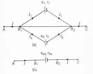
Consider two cells of EMFs $E_1$ and $E_2$ which are to be compared.
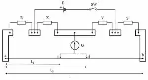
The positive terminals of both cells are connected to terminal A of the resistive wire of the potentiometer and the negative terminals of the cells are connected to the terminal X and Z of a two-way key, while its common potential is connected to the jockey through the galvanometer (G). See figure above.
The driver cell (E), rheostat (Rh), and the one-way key are connected to terminals A and B to the resistive wire of the potentiometer.
Now to compare the EMFs of two cells keep the current constant through the resistive wire A and B by using the rheostat.
Let’s connect the jockey to the cell $E_1$ by closing the key X and Y. Now, slide the jockey on the resistive wire to obtain the null deflection on the galvanometer, let C is the point on the resistive wire which gives the null point and it is at distance $l_1$ from the point A. Then the EMF ($E_1$) of the cell is given as-
\begin{equation}E_1=(xl_1)I\end{equation}
Where x = resistance per unit length of potentiometer resistive wire and $l_1$ is the balancing length.
Now, similarly, connect the jockey to the cell $E_2$ by closing the key Z and Y and once again slide the jockey to obtain the balance point on the resistive wire. Let C is the balance point which is at distance $l_2$ from point A. Then the EMF of the cell ($E_2$) is given as-
\begin{equation}E_2=(xl_2)I\end{equation}
Now, from the equation (1) and (2), we get-
$$\frac{E_1}{E_2}=\frac{l_1}{l_2}$$
Hence, if we know the EMF of one cell then from this equation we can find the EMF of the other cell accurately. Watch this experiment, in this experiment you will how to compare the EMFs of two cells.
TO MEASURE THE INTERNAL RESISTANCE OF THE CELL
You can see in the above figure that a resistance box with a key is connected to the standard cell. It is done because we could find the potential difference between the terminals of the standard cell.
To find the internal resistance (r) of the cell of EMF (E), let $E_p$ is the driver cell and constant current is maintained in the circuit with the help of rheostat.
Let’s slide the jockey over the resistive wire without using the resistance box or without closing the key $K_2$. Suppose C is the balancing point on the resistive wire and $l_1$ is the balancing length from point A, then the EMF of the $E_1$ is –
\begin{equation}E_1=(xl_1)I\end{equation}
Now this time closed the key of the resistance box and slide the jockey to obtain the balance point. Suppose C is the balance point and $l_2$ is the balancing length from point A. Then the potential difference across the terminals of the cell (E) is-
\begin{equation}V=(xl_2)I\end{equation}
Dividing equation (1) by equation (2), we have-
$$\frac{E}{V}=\frac{l_1}{l_2}$$
The internal resistance of the standard cell (E) is given by-
$$r=\left(\frac{E}{V}-1\right)R$$
Where R is the resistance of the resistance box and r is the internal resistance of the standard cell. Now substituting the value of $\displaystyle{\frac{E}{V}}$ in the above equation, we get-
$$r=\left(\frac{l_1}{l_2}-1\right)R$$
TO MEASURE THE VOLTAGE ACROSS THE BRANCH OF A CIRCUIT
It is very easy to measure the voltage across the branch of a circuit with the help of a potentiometer. To measure the value, first, you have to adjust the rheostat in such a way that the constant current flows through the resistor so that it creates a specific voltage drop per unit length of the resistor.
Now let’s connect one end of the branch to point A of the resistive wire and another end is connected to the jockey through the galvanometer. It is free to slide over the resistive wire. Now, slide the jockey over the resistive wire until the galvanometer shows zero deflection.
When the galvanometer show null deflection then note down the reading of the position of the sliding contact tip on the resistive scale and according to the observed values we can measure the voltage across the branch of the circuit. And we have already adjusted the voltage per unit length of the resistive wire.
SENSITIVITY OF THE POTENTIOMETER
Sensitivity of the potentiometer means, what is the smallest potential difference that can be measured with the help of the potentiometer.
There are two ways to describe its sensitiveness.
- When the EMF of the driver cell is fixed- For the same voltage of the driver cell if we increase the length of the potentiometer’s resistive wire then the length of the resistance per unit voltage gets increased. Hence, the sensitivity of the potentiometer gets increased. So universally, we can say the sensitivity of a potentiometer is directly proportional to the length of the resistance.
- When the resistive wire of the fixed-length – If we reduce the voltage of the driver cell keeping the resistive wire of the potentiometer at a fixed length, then the voltage per unit length of the resistive wire gets decreased. Hence, the sensitivity of the potentiometer gets increased. So universally we can say that the sensitivity of the potentiometer is inversely proportional to the EMF of the driver voltage.
Stay tuned with Laws Of Nature for more useful and interesting content.

![Wheatstone bridge | working principle, construction and its derivation [class 12].](/storage/2021/06/wheatstone-bridge-300x240.jpg)